|
|
 |
|
|
| |
|
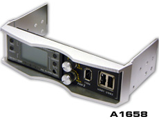
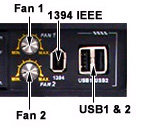
Design for 5.25 drive bay |
|
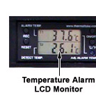
Temp. alarm LCD monitor
malfunction |
|
2 adjustable fan speed controllers |
|
1394 firewire, 2.0 USB*2 |
 |
Aluminum housing |
|
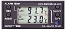
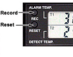
When the screen is shown MAX, it means
the highest temperature you have recorded. In the
meanwhile, T1 is the highest temperature you set,
T2 is the highest temperature that the sensor detected.
|
|
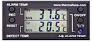
On the other hand, MIN means the lowest
temperature that have been recorded.
|
|
|
|
|
 |
If the fan unit you wish to
control is over 0.35Amp, please connect it
to Speed Controller # 1. However, the total
current of fan unit is less than 0.35Amp,
please connect it to Fan2. |
|
If you wish to control a fan
unit with a 3pin power connection, please
use the included CPU Fan Adaptor. Once connected,
you may still monitor the RPM by connecting
the Yellow wire directly to motherboard. |
|
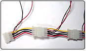 |
An efficient way to
control the fan units is to chain connect each Silent
Fan Units. |
 |
Then attach this set
to one of the Speed Controllers. |
|
If 4 or more
Silent Fan Units are chain connected altogether, please
attach the set to either Speed Controller #2 or #3.
This is because each Silent Fan Unit requires 0.10Amp:
[0.1Amp X 4 Silent Fan Units] is greater than 0.35Amp,
so it must be connected to Fan2 or Fan3 only.
|
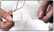
USB2.0 connection:
it is compatible for USB1.1
Please consult your motherboard manual to find out
the position of USB 2.0 connection on your motherboard. You can see 9-pins from Hardcano USB2.0.
USB2.0 connection:
it is compatible for USB1.1 |
VCC1 connects to VCC1 or USB+5V or USB Power on
your M/B.
DATA-1 connects to USB1- or LDM1 or
USB2- on your M/B.
DATA+1 connects to USB1+ or LDP1 or
USB2+ on your M/B
GND1 connects to GND1 or GND.
SHIELD connects to NG on your M/B.
VCC2 connects to VCC2 or USB+5V or
USB Power on your M/B.
DATA-2 connects to USB2- or LDM2 or
USB3- on your M/B.
DATA+2 connects to USB2+ or LDP2 or
USB3+ on your M/B
|
Note: one or two pins
may be shown in both rows
as NC on some motherboards, please ignore it,
NC means empty pin |
IEEE firewire
connection |
| Identify and
find out IEEE 1394 port in the I/O shield
(back side of the case), then connect the
IEEE 1394 to it.
If you can not find IEEE 1394 port from
I/O shield but exist IEEE 1394 function,
please install PCI bracket with IEEE 1394
(usually enclosed in the motherboard package),
then connect it.
|
|
|

|
|
 |
|
|
Copyright (c) 2005 Thermaltake Technology Co., Ltd. All Rights Reserved. |
"Tt", Thermaltake, Thermaltake are trademarks of Thermaltake Technology Co., Ltd.
All other registered trademarks belong to their respective companies. |
|